Build an ontology from a semantic model in Fabric IQ
There are two ways to build a Fabric IQ ontology: manually, by creating each entity type and relationship from scratch, or automatically, by generating the structure from a Power BI semantic model. This lab uses the semantic model approach.
In this lab, you’ll load sample data for a fictitious healthcare company into a lakehouse and eventhouse, build a semantic model on top of it, and then generate an ontology from that model. The sample data represents hospitals, departments, rooms, patients, vital sign equipment, and vital signs readings. Each table in the semantic model becomes an entity type, and each relationship between tables becomes a relationship type in the ontology.
[!IMPORTANT] Ontology in Microsoft Fabric is currently in preview.
This lab takes approximately 45 minutes to complete.
Tip: For related training content, see Create an ontology in Microsoft Fabric.
Note: You need access to a Fabric paid or trial capacity to complete this exercise. For information about the free Fabric trial, see Fabric trial. You’ll also need to enable the following tenant settings: Enable Ontology item (preview) and User can create Graph (preview).
Create a workspace
- Navigate to the Microsoft Fabric home page at
https://app.fabric.microsoft.com/home?experience=fabricin a browser, and sign in with your Fabric credentials. - In the menu bar on the left, select Workspaces (the icon looks similar to 🗇).
- Create a new workspace with a name of your choice, selecting a licensing mode in one of the following workspace types: Fabric, Fabric Trial, or Power BI Premium.
- When your new workspace opens, it should be empty.
Create a lakehouse with sample data
Now you’ll create a lakehouse and load hospital operations data that will form the basis of your ontology.
- In your workspace, select + New item > Lakehouse.
- Name the lakehouse
LamnaHealthcareLHand select Create. - When the lakehouse opens, you’ll upload CSV files and convert them to tables.
Download and load the hospital data files
You’ll download sample CSV files, upload them to the lakehouse, and convert them to tables.
- Download sample-data.zip and extract the CSV files to your local computer. The ZIP file contains:
- Hospitals.csv - Healthcare facilities in your network
- Departments.csv - Hospital departments (ICU, Emergency, Surgical)
- Rooms.csv - Individual rooms within departments
- Patients.csv - Current patients and their room assignments
- VitalSignEquipment.csv - Monitoring equipment assigned to patients (which patient is being monitored, and when monitoring started)
- VitalSignsReadings.csv - Patient vital sign measurements (heart rate, oxygen levels, respiratory rate) collected over time from the vital sign equipment
- Upload the five lakehouse files:
- In the lakehouse, select Upload files from the main view
- Browse to and select these five files: Hospitals.csv, Departments.csv, Rooms.csv, Patients.csv, VitalSignEquipment.csv
- Select Open
- Select Upload to upload all five files at once
- Wait for the upload to complete
Note: Do not upload VitalSignsReadings.csv to the lakehouse. You’ll load it to the eventhouse in the next section, where it belongs as time-series data.
- Convert each uploaded file to a table:
- In Explorer, select the Files folder, where you should see all five CSV files
- For each file, select the ellipsis (…) to the right of the file name
- Select Load to Tables > New table
- Configure the table:
- Table name: Fabric pre-fills this from the filename with a lowercase first letter (e.g.,
hospitals,departments,rooms,patients,vitalSignEquipment). - Column header: Check Use header for column names
- Separator: Leave as comma (
,)
- Table name: Fabric pre-fills this from the filename with a lowercase first letter (e.g.,
- Select Load
- Repeat this process for all five files
- Verify you have five tables in the Tables section:
hospitals,departments,rooms,patients, andvitalSignEquipment.
Create an eventhouse with streaming data
Next, you’ll create an eventhouse to store real-time vital signs data as a time-series entity in your ontology.
- In your workspace, select + New item > Eventhouse.
- Name the eventhouse
LamnaHealthcareEHand select Create. - A default KQL database is created with the same name. Select the KQL database to open it.
Ingest vital signs data
- Select the KQL database
LamnaHealthcareEH, then select Get data > Local file. - In the Select or create a destination table section, select + New table and enter
VitalSignsReadingsas the table name. - Under Add up to 1,000 files, select Browse for files and upload the VitalSignsReadings.csv file you downloaded earlier.
- Select Next, then continue through the ingestion wizard, keeping the default settings.
- Select Finish to complete the ingestion.
- Verify the VitalSignsReadings table appears in the KQL database with 20 rows.
Create a semantic model
Now you’ll create a Power BI semantic model from your lakehouse. As you define each relationship, think about what it means in the real world: a department belongs to a hospital, a room is part of a department, a patient is admitted to a room, and a piece of equipment is assigned to a patient. These business relationships are exactly what ends up in the ontology.
-
In your workspace, open the LamnaHealthcareLH lakehouse.
-
From the lakehouse ribbon, select New semantic model.
-
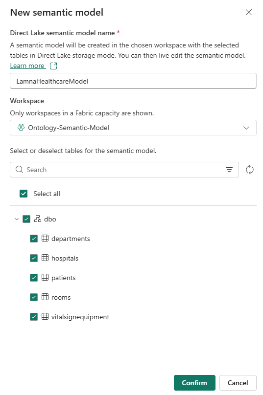
In the New semantic model dialog, as shown below:
- In the Direct Lake semantic model name field, enter
LamnaHealthcareModel. - Select all five tables: hospitals, departments, rooms, patients, vitalSignEquipment.
- Select Confirm.
Note: If the tables don’t appear in the list, refresh your browser and try again.
- The semantic model opens directly, showing your five tables.
- In the Direct Lake semantic model name field, enter
### Define relationships between tables
Relationships in the semantic model define how tables connect to each other. These relationships become the relationship types in your ontology.
-
In the ribbon, select Manage relationships > + New relationship.
- Create the first relationship with these settings, then select Save:
-
From table: departments Column: HospitalId -
To table: hospitals Column: HospitalId - Cardinality: Many to one (*:1)
- Cross filter direction: Both
- Select Save
-
-
Select + New relationship again and create three more relationships:
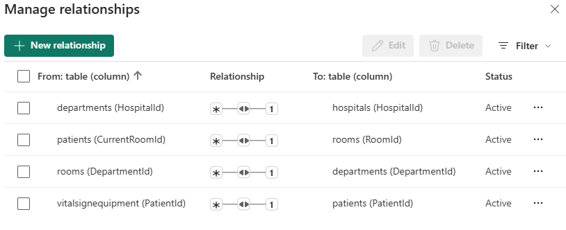
From table From column To table To column rooms DepartmentId departments DepartmentId patients CurrentRoomId rooms RoomId vitalsignequipment PatientId patients PatientId Use the same settings for each: cardinality Many to one (*:1), cross filter Both, then Save.
-
Verify your Manage relationships pane shows exactly 4 active relationships, matching the image below, then select Close.
-
In the top navigation bar, select the × next to LamnaHealthcareModel to close the semantic model. Return to your workspace item list.
- In your workspace item list, select the ellipsis (…) next to LamnaHealthcareModel and select Open semantic model.
Generate the ontology
Now that your semantic model is ready and your lakehouse data is in place, you’ll generate the ontology from the semantic model editor. The semantic model captures your static hospital data — hospitals, departments, rooms, patients, and vital sign equipment. The eventhouse vital signs readings data is time-series data, which is added to the ontology manually after generation.
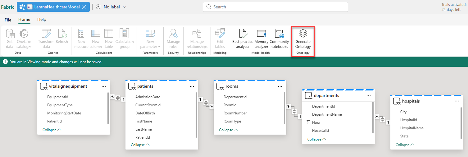
-
From the top ribbon, select Generate Ontology.
-
Select your workspace name from the drop-down box.
-
In the name dialog, enter
LamnaHealthcareOntology, then select CreateTip: Ontology names can include numbers, letters, and underscores — no spaces or dashes.
Wait a few moments while the system is Generating Ontology.
The system generates 5 entity types (Hospitals, Departments, Rooms, Patients, VitalSignEquipment) with all their properties and 4 relationship types based on the semantic model relationships. The VitalSignEquipment entity has static properties from the lakehouse, but doesn’t yet have the time-series vital signs readings from the eventhouse — you’ll add that as a second binding after configuring the relationship bindings.
After generating the ontology, you need to complete the following tasks manually:
- Review entity type keys and add any that are missing
- Verify and configure relationship types so the relationships are queryable
- Add time-series binding to VitalSignEquipment for real-time vital signs data
You’ll complete these tasks in the sections below.
Review and add entity type keys
Each entity type needs a key property that uniquely identifies each instance. During ontology generation, keys are inferred from the semantic model’s relationship structure. Depending on each table’s role in relationships, some keys are inferred automatically while others need to be added manually. Verify that each entity type has a key defined.
- In the Entity Types list, select hospitals.
- In the Entity type configuration pane, under Key properties, verify a HospitalId key is defined.
- If no key appears, select + Add key, choose HospitalId, and select Save.
-
Verify and add keys as needed for the remaining entity types:
Entity type Key property departments DepartmentId rooms RoomId patients PatientId vitalsignequipment EquipmentId
Verify and configure relationship types
The generated ontology includes relationship type definitions. During generation, relationship bindings to source data are created based on the semantic model structure. Depending on how the semantic model defines keys and relationships, some bindings are configured automatically while others require manual setup. You’ll verify each relationship and configure any that need it.
Understanding relationship configuration:
A relationship binding connects a relationship type to source data. You select a data table that contains columns identifying both entity types — essentially a foreign key relationship. The system uses two columns from this table to match entity instances on both sides of the relationship.
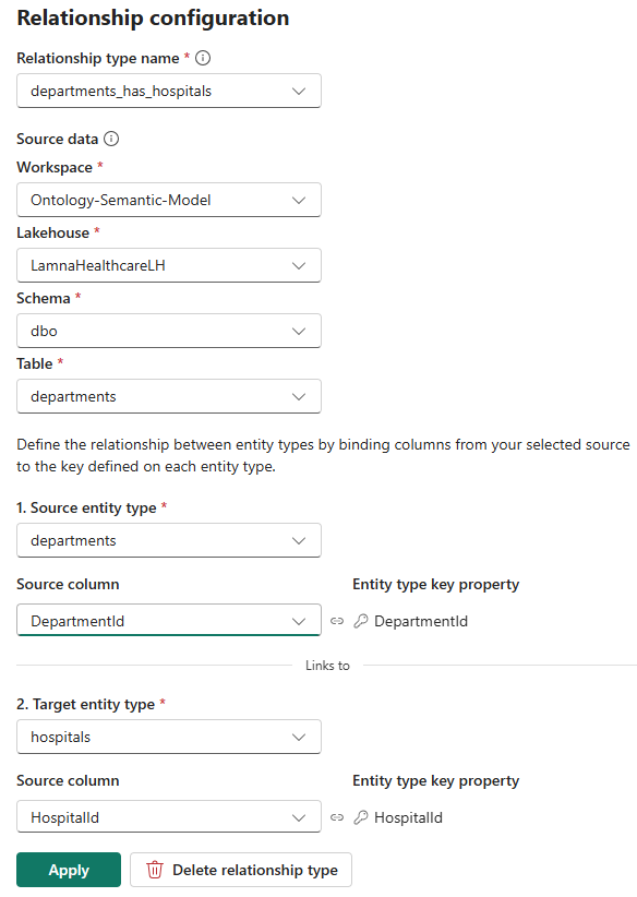
The image below shows a configured relationship using the departments table:
- Section 1 (Source entity type):
DepartmentId— identifies the department instance - Section 2 (Target entity type):
HospitalId— identifies which hospital the department belongs to
Now let’s check the relationships in your ontology:
- In the ontology canvas, select the departments entity in the Entity Types navigation bar.
- Select the relationship line between Departments and Hospitals to open the Relationship configuration pane.
- Check the Source data section:
- If already configured: The pane shows workspace, lakehouse, schema, table, and both column mappings. Verify the configuration matches the image above.
- If not configured: The source data fields are empty. Follow the configuration steps below.
Configure Departments–Hospitals relationship
If the relationship requires configuration, complete these steps:
- In the Relationship configuration pane, configure the source data location:
- Workspace: Select your workspace
- Lakehouse: Select LamnaHealthcareLH
- Schema: Select dbo
- Table: Select Departments
Note: Select the Departments table (not Hospitals) because it contains both the department identifier and the hospital reference. The Hospitals table has no column pointing back to departments, so it can’t express the direction of the relationship.
- Configure the entity type mappings:
- Under 1. Source entity type: Select Departments
- Source column: Select DepartmentId
- Under 2. Target entity type: Select Hospitals
- Source column: Select HospitalId
- Under 1. Source entity type: Select Departments
- Select Apply or Create.
Verify remaining relationships
Verify the remaining three relationships. Configure any that require setup using the values in the table below:
| Relationship | Source table | Source entity table: column | Target entity table: column |
|---|---|---|---|
| rooms_has_departments | LamnaHealthcareLH > dbo > Rooms | Rooms: RoomId | Departments: DepartmentId |
| patients_has_rooms | LamnaHealthcareLH > dbo > Patients | Patients: PatientId | Rooms: CurrentRoomId |
| vitalsignequipment_has_patients | LamnaHealthcareLH > dbo > VitalSignEquipment | VitalSignEquipment: EquipmentId | Patients: PatientId |
With all four relationships verified and configured, your ontology understands the complete healthcare data model: hospitals contain departments, departments contain rooms, patients are admitted to rooms, and vital sign equipment is assigned to patients.
Add time-series binding to VitalSignEquipment
The VitalSignEquipment entity currently has only static properties from the lakehouse (EquipmentId, PatientId, EquipmentType, MonitoringStartDate). Now you’ll add a second binding to attach time-series vital signs readings from your eventhouse. This allows a single entity to combine static reference data with real-time streaming measurements.
-
In the Entity Types list, select vitalsignequipment.
-
In the Entity type configuration pane, go to the Bindings tab. You’ll see the existing static binding from the lakehouse.
-
Select Add data to entity type to add a second binding.
-
In the OneLake catalog, locate LamnaHealthcareEH (eventhouse) in your workspace and select it.
-
Select Add.
-
Select the VitalSignsReadings table and select Next.
-
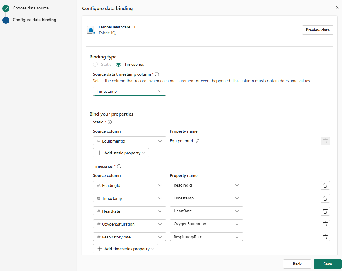
For Binding type, select Time series.
-
For Source data timestamp column, select Timestamp.
[!IMPORTANT] Time-series bindings require a matching key from static data. The static binding you already have provides EquipmentId as the key to link streaming readings to equipment entities.
- Configure the time-series binding:
- Static section - Maps the key to link streaming data to entities:
- Select EquipmentId as the column that connects streaming readings to equipment entities
- This matches the EquipmentId from your static binding
- Time series section - Map the properties to columns (should auto-map):
- ReadingId → ReadingId
- Timestamp → Timestamp
- HeartRate → HeartRate
- OxygenSaturation → OxygenSaturation
- RespiratoryRate → RespiratoryRate
Your configuration should look like this:
- Static section - Maps the key to link streaming data to entities:
- Select Save to create the time-series binding.
Your VitalSignEquipment entity now has both static reference data (which equipment monitors which patient) and time-series data (actual vital sign readings over time).
Your ontology now has 5 entity types and 4 relationships, with all entity data and relationship bindings fully configured.
Preview the ontology
Your ontology is now complete with static entities from the lakehouse and time-series data from the eventhouse, all connected through four relationships.
- Select Rooms from the Entity Types list.
- In the ontology ribbon, select Entity type overview.
-
You’ll see an “Updating your ontology” message while the system processes your data in the background. After 1-2 minutes, refresh your browser to display the entity type overview.
You’ll see tiles showing:
- Relationship graph: Visual representation of how this entity type connects to other entity types
- Property charts: Bar charts showing the distribution of property values (like RoomType, RoomNumber, or DepartmentId)
- Entity instances table: List of all individual room instances with their properties
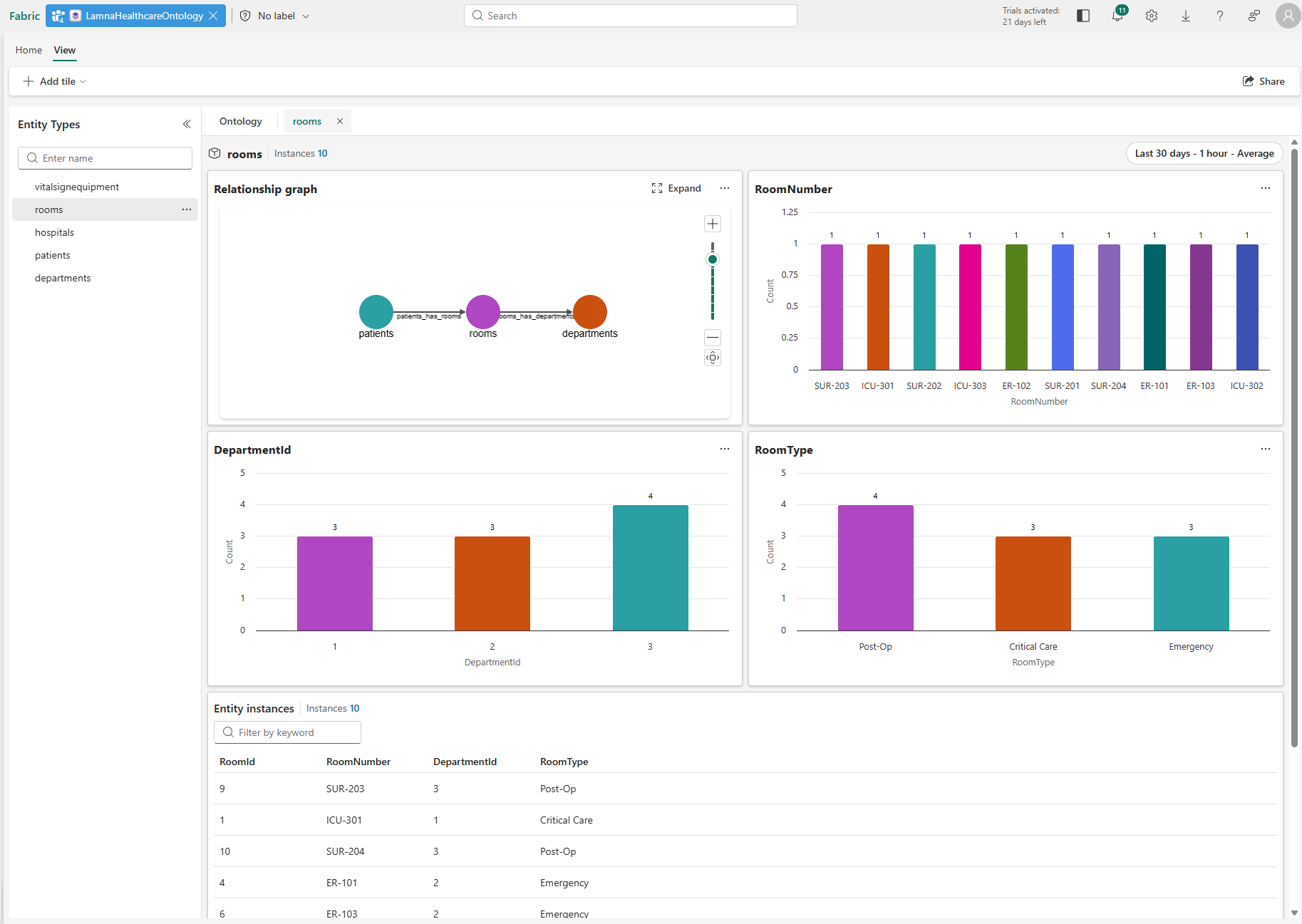
- In the Entity instances table, select any room instance (for example, ICU-302).
- The instance view opens, showing the properties for this specific room and its connections to other entities.
You’ve successfully created a complete ontology by building a semantic model from your lakehouse, generating the ontology structure automatically, extending it with time-series data from an eventhouse, and connecting everything with relationship bindings. Your ontology now represents the healthcare domain with:
- 5 entity types: Hospitals, Departments, Rooms, Patients, VitalSignEquipment
- 4 relationships: all bound to source data and fully queryable
- Static + time-series data: VitalSignEquipment combines lakehouse reference data with eventhouse streaming measurements
Clean up resources (optional)
You can keep this workspace and ontology to continue exploring Fabric IQ capabilities. If you want to remove the resources you created in this exercise, follow these steps:
- In the bar on the left, select the icon for your workspace to view all of the items it contains.
- Select Workspace settings.
- In the General section, select Remove this workspace.